Do you know how to get a LED to fade on ESP32-S3 correctly? Adding that smooth, breathing effect is a popular way to give your project visual flair – maybe for status indication or just that cool factor everyone wants. When implemented properly, this feature adds a professional touch and performs reliably for years. But if you, as the developer, haven't done your homework on the ESP32-S3's specifics (especially its powerful LEDC hardware), you'll wish you'd stuck to simple blinking! Here’s what goes into doing that homework right for a perfect LED fade.
Understanding PWM and ESP32's LEDC
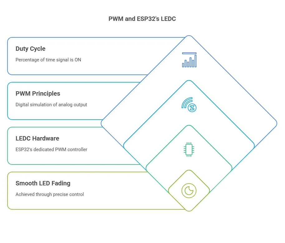
Getting that smooth LED fade isn't just about copying code. If you want to avoid flicker, ensure efficiency, and actually leverage the power of your ESP32-S3, you first need to grasp the underlying principles: Pulse Width Modulation (PWM) and why the ESP32's specialized LED Control (LEDC) peripheral is the right tool for this job. Skipping this groundwork leads directly to frustration and subpar results.
What is PWM?
Pulse Width Modulation (PWM) is the standard technique microcontrollers use to simulate analog output levels with purely digital signals. Since a pin can only be fully ON (3.3V) or fully OFF (0V), PWM rapidly switches the pin between these states. The key is the duty cycle – the percentage of time the signal stays ON within a fixed cycle. A higher duty cycle results in a higher average voltage, making an LED brighter. It’s a digital trick to achieve analog-like control.
How PWM Creates the Fading Effect
The fading effect comes from dynamically changing that duty cycle over time. To fade an LED in, you programmatically increase the duty cycle – say, from 0% (off) smoothly up to 100% (fully bright). To fade out, you do the reverse. The ESP32 calculates and applies these changing duty cycles very quickly. If this change is gradual enough, our eyes perceive a smooth transition in brightness, not the rapid ON/OFF switching that's actually happening.
Why ESP32's LEDC Hardware is Superior
Here’s where knowing your hardware pays off. While basic PWM can be done in software, the ESP32 family features a dedicated LEDC (LED Control) peripheral. Using this hardware offers significant advantages you simply don't get with software emulation:
- CPU Freedom: The LEDC hardware handles the demanding task of generating precise pulse trains independently. This frees your main processor (CPU) to handle other critical tasks in your application, preventing slowdowns or timing conflicts. Relying on software PWM can quickly consume CPU resources.
- Precision and Flexibility: LEDC provides fine-grained control over both the PWM frequency and the duty cycle resolution (the number of brightness steps). This hardware-level control is crucial for achieving truly smooth fades and avoiding the visible stepping or flickering that can plague simpler software PWM methods.
- Scalability with Channels: The ESP32 typically offers multiple independent LEDC channels (often 8 or 16). Each channel can drive a separate PWM output on a different GPIO pin with its own frequency and resolution settings. This makes controlling multiple fading LEDs simultaneously feasible and efficient, something that quickly becomes unwieldy and resource-intensive with software PWM.
Attempting professional-looking fades, especially on multiple LEDs, without using the LEDC hardware on an ESP32 is working against the chip's design. You use the right tool for the job – here, that's the LEDC peripheral.
Key LEDC Parameters Explained (Channel, Frequency, Resolution)
To effectively use ledcWrite() and related functions later, you must configure these LEDC parameters correctly during setup using ledcSetup(). Getting them wrong directly impacts performance and visual quality:
- Channel: An independent hardware timer/counter for generating a PWM signal. You pick an available channel (0-7 or 0-15 typically), configure it, and then link it to a GPIO pin. Using separate channels is essential for controlling multiple LEDs independently.
- Frequency (Hz): How many times the PWM cycle repeats per second. For LEDs, setting this too low (e.g., < 100Hz) causes noticeable flicker. Setting it unnecessarily high can limit the maximum achievable resolution. A range like 1kHz to 5kHz usually balances smoothness with performance well for visual effects.
- Resolution (bits): Determines the number of distinct duty cycle steps available, impacting fade smoothness. 8-bit resolution (2^8 = 256 steps) is often adequate, while 10-bit (1024 steps) or 12-bit (4096 steps) offers even finer control. The maximum resolution is interdependent with the chosen frequency. You need to know the resolution to correctly map your desired brightness (0-100%) to the actual duty cycle values used in ledcWrite() (e.g., 0-255 for 8-bit, 0-1023 for 10-bit).
ledcWrite vs. analogWrite on ESP32
Many coming from basic Arduino platforms reach for analogWrite(). On ESP32, while analogWrite() exists for compatibility, it functions as a simplified interface to the LEDC peripheral, often using default settings for frequency and resolution that might not be optimal for your specific needs. To ensure you have explicit control over the channel, frequency, and resolution – parameters critical for performance and smoothness as discussed above – use the ESP32-specific LEDC functions: ledcSetup(), ledcAttachPin(), and ledcWrite(). This avoids ambiguity and guarantees you are configuring the hardware precisely as intended.
Preparing Your Hardware and Software
With the 'why' and 'what' covered, let's transition to the 'how'. Proper preparation here is foundational. A wrong component value or a missed software step is like starting a tile job on an unstable substrate – the problems will inevitably show up in the final result.
Hardware You'll Need
Assemble these items carefully. Precision matters.
- ESP32-S3 Development Board: Double-check it's the S3 variant.
- LED: Standard type.
- Current-Limiting Resistor: Non-negotiable for LED health. Typically 220Ω or 330Ω for standard LEDs on a 3.3V GPIO. Omitting this or using a drastically wrong value will destroy the LED due to overcurrent.
- Breadboard & Jumper Wires: For reliable, solderless connections.
- USB Cable: Quality matters for stable power and data transfer.
Software Setup
Your computer needs the correct tools configured to recognize and program the ESP32-S3.
- Arduino IDE: Install a recent version from arduino.cc.
- ESP32 Board Support Package: This is not optional. The IDE needs the specific compilers, tools, and libraries for the ESP32 family. Install it via the Boards Manager (Tools > Board > Boards Manager, search "esp32", install Espressif Systems package) after adding the correct JSON URL in Preferences. Without this package, the IDE won't recognize your board or compile ESP32-specific code (like the ledc functions).
Wiring the LED to Your ESP32-S3
Follow this precisely. Loose connections or incorrect polarity are primary failure points.
- GPIO Pin Selection: Consult your specific board's pinout diagram. While many S3 GPIOs support LEDC, some have limitations or default uses (like strapping pins). Pick a general-purpose one; we'll use GPIO 2 as a common example, but verify its suitability for your board.
- Resistor to GPIO: Connect one leg of the resistor to the chosen GPIO pin (e.g., GPIO 2).
- Resistor to LED Anode (+): Connect the resistor's other leg to the LED's longer leg (Anode).
- LED Cathode (-) to GND: Connect the LED's shorter leg (Cathode) to a GND pin on the ESP32-S3. Reversing LED polarity means it simply won't light up.
Tip: Ensure jumper wires fit snugly in the breadboard and make good contact with the ESP32 pins.
Configuring the Arduino IDE
Final check before coding: ensure the IDE targets your specific hardware.
- Board Selection: Tools > Board > ESP32 Arduino. Select the exact ESP32-S3 board model you have. Choosing the wrong profile can cause compile errors or upload failures because pin mappings or memory layouts might differ.
- Port Selection: Tools > Port. Select the serial port corresponding to your connected ESP32-S3. If the correct port isn't selected, the IDE cannot communicate with the board to upload code.
How to Get a LED to Fade on ESP32-S3
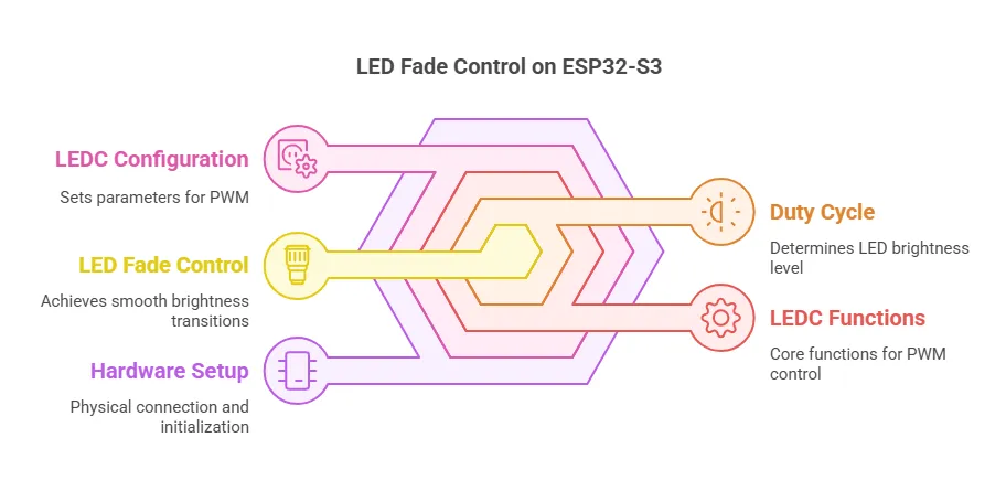
Now for the part you've been waiting for – the actual code. Remember all that groundwork about LEDC parameters? This is where it pays off. Using the correct functions and understanding how they work together is the difference between a clean, professional fade and a flickering mess. Here’s a solid example using the ESP32's dedicated LEDC functions.
Complete Arduino Code Example (Using ESP32 LEDC functions)
`// Define LED Pin const int ledPin = 2; // GPIO pin connected to the LED anode (via resistor) - VERIFY for your board!
// LEDC Channel, Frequency, and Resolution Configuration const int ledChannel = 0; // Use LEDC channel 0 const int freq = 5000; // PWM frequency in Hz (5kHz is a good starting point) const int resolution = 8; // 8-bit resolution (0-255 duty cycle range)
// Variables for fading int dutyCycle = 0; int fadeAmount = 5; // How much to change the duty cycle each step
void setup() { // Configure the LEDC peripheral // ledcSetup(channel, frequency, resolution_bits); ledcSetup(ledChannel, freq, resolution);
// Attach the channel to the GPIO pin // ledcAttachPin(gpio_pin, channel); ledcAttachPin(ledPin, ledChannel);
// Optional: Initialize Serial Monitor for debugging Serial.begin(115200); Serial.println("ESP32-S3 LED Fade Example Initialized"); }
void loop() { // Increase the LED brightness (fade in) for (dutyCycle = 0; dutyCycle <= 255; dutyCycle += fadeAmount) { // Set the LEDC duty cycle ledcWrite(ledChannel, dutyCycle); // Wait a bit for the eye to perceive the change delay(30); // Adjust delay for different fade speeds }
// Decrease the LED brightness (fade out) for (dutyCycle = 255; dutyCycle >= 0; dutyCycle -= fadeAmount) { // Set the LEDC duty cycle ledcWrite(ledChannel, dutyCycle); // Wait a bit delay(30); // Keep delay consistent for symmetrical fade }
// Small pause at the bottom (optional) // delay(500); }`
Explaining the ESP32-S3 Fade Code
Let's break down that code. It’s not complex, but each part plays a specific role in achieving the smooth fade using the ESP32's hardware capabilities correctly.
Code Structure (Defines, setup, loop)
- Constants/Variables (const int, int): At the top, we define key parameters: the GPIO pin (ledPin), the chosen LEDC channel (ledChannel), PWM frequency (freq), and resolution (resolution). We also declare variables for the current dutyCycle and the fadeAmount (how big each step in brightness change is). Defining these upfront makes the code easier to read and modify. Crucially, verify ledPin matches your actual wiring.
- setup(): This function runs once when the ESP32-S3 powers up or resets. Its job here is critical:
- ledcSetup(): Configures the specified LEDC channel with the desired frequency and resolution. This must be done before attaching the pin.
- ledcAttachPin(): Connects the configured LEDC channel to the physical GPIO pin you wired the LED to. Without this, the channel works internally but doesn't drive the pin.
- Serial.begin(): (Optional but recommended for debugging) Initializes serial communication so you can print messages back to your computer via the Arduino Serial Monitor.
- loop(): This function runs repeatedly after setup() completes. It contains the logic for the continuous fading effect:
- Two for loops control the fading in and fading out by systematically adjusting the dutyCycle.
- ledcWrite(): Inside the loops, this function actually sets the brightness by applying the current dutyCycle value to the configured LEDC channel.
- delay(): Small pauses within the loops slow down the fade, making it visible and smooth to the human eye.
Dissecting ledcSetup() (Channel, Freq, Resolution)
ledcSetup(ledChannel, freq, resolution);
This is the core configuration call for the LEDC hardware channel.
- ledChannel (e.g., 0): Selects which hardware channel to configure. Remember, you have multiple available (check ESP32-S3 datasheet for exact number, often 8 low-speed, 8 high-speed).
- freq (e.g., 5000): Sets the PWM frequency in Hz. 5000 Hz (5kHz) is generally well above human flicker perception and works well for LEDs.
- resolution (e.g., 8): Defines the duty cycle range in bits. 8 bits means the duty cycle will range from 0 to 2^8 - 1 = 255. If you chose 10 bits, the range would be 0 to 1023. This choice directly impacts the maximum value you use in ledcWrite().
Understanding ledcAttachPin() (Pin Mapping)
ledcAttachPin(ledPin, ledChannel);
This function makes the physical connection. It tells the ESP32: "Route the output signal generated by ledChannel (which we just configured with ledcSetup) to the physical pin specified by ledPin." It's a straightforward but essential step – forget this, and your LED stays dark.
Using ledcWrite() for Brightness Control
ledcWrite(ledChannel, dutyCycle);
This is the function you call repeatedly to change the LED's brightness.
- ledChannel (e.g., 0): Specifies which configured channel's duty cycle you want to change.
- dutyCycle (e.g., values from 0 to 255 in our code): Sets the desired duty cycle (brightness). Crucially, the valid range for this value depends directly on the resolution set in ledcSetup(). For 8-bit resolution, the range is 0 (fully off) to 255 (fully on). For 10-bit, it's 0 to 1023. Sending a value outside the configured range might result in unexpected behavior (often clamping to the max value).
The Fading Logic Explained
The continuous fade is achieved by the two for loops in loop():
- Fade In Loop: for (dutyCycle = 0; dutyCycle <= 255; dutyCycle += fadeAmount)
- Starts dutyCycle at 0.
- Continues as long as dutyCycle is less than or equal to 255 (our max for 8-bit resolution).
- In each iteration, it calls ledcWrite() to set the current brightness, waits briefly using delay(30), and then increases dutyCycle by fadeAmount (e.g., 5). This gradually steps the brightness up.
- Fade Out Loop: for (dutyCycle = 255; dutyCycle >= 0; dutyCycle -= fadeAmount)
- Starts dutyCycle at the maximum brightness (255).
- Continues as long as dutyCycle is greater than or equal to 0.
- Sets the brightness with ledcWrite(), waits with delay(30), and then decreases dutyCycle by fadeAmount. This gradually steps the brightness down.
The delay(30) calls are important. Without them, the loops would execute so fast that the fade would appear almost instantaneous. Adjusting the delay() value (or the fadeAmount) allows you to control the speed of the fade effect. Smaller delays or larger fade amounts result in faster fades.
Uploading and Running Your Sketch
You've got the hardware wired, the IDE configured, and the code written. Time to bring it to life.
Steps to Upload to ESP32-S3
- Connect: Ensure your ESP32-S3 board is connected to your computer via the USB cable.
- Verify Settings: Quickly double-check that the correct Board and Port are selected under the Tools menu in the Arduino IDE.
- Compile/Verify: Click the checkmark icon (✓) in the Arduino IDE toolbar. This compiles your code and checks for syntax errors before attempting to upload. Fix any errors reported in the console output area at the bottom.
- Upload: Click the right-arrow icon (→) in the Arduino IDE toolbar. The IDE will compile the code again and then attempt to upload it to the ESP32-S3.
- You should see messages in the console indicating the connection progress ("Connecting........_____.....").
- Some ESP32-S3 boards automatically enter bootloader mode for flashing. Others might require you to hold down the BOOT button, press and release the RESET (or EN) button, then release the BOOT button right as the "Connecting..." message appears if the automatic process fails. Consult your specific board's documentation if uploads consistently fail.
- Wait for Completion: The upload process takes a few moments. Once finished, you should see a "Done uploading." message in the IDE. The ESP32-S3 will typically reset automatically and start running your new code.
Observing the LED Fade Effect
If everything went correctly – the wiring is solid, the code is right, and the upload succeeded – you should now see the LED connected to your chosen GPIO pin (e.g., GPIO 2) start to smoothly glow brighter, reach full brightness, then smoothly dim down to off, and repeat the cycle continuously. Congratulations, you've successfully implemented hardware PWM fading on your ESP32-S3 the right way!
Troubleshooting Common ESP32 LED Fading Problems
Even with careful preparation, things can sometimes go sideways. Don't get discouraged; troubleshooting is part of the process. Here are some common issues you might encounter when getting an LED to fade on the ESP32-S3 and how to tackle them systematically. Think of this as your checklist before calling it a failed job.
LED Issues (No light, Always on/off)
- No Light at All:
- Check Wiring: This is the #1 culprit. Verify every connection: GPIO pin to resistor, resistor to LED anode (+, longer leg), LED cathode (-, shorter leg) to a GND pin on the ESP32. Ensure wires are fully seated in the breadboard and making contact.
- Check Polarity: Is the LED inserted correctly? The longer leg (anode) should connect towards the GPIO pin (via the resistor), the shorter leg (cathode) towards GND. Reversing it stops current flow.
- Check Resistor: Is the resistor value correct? Too high a value might make the LED too dim to see easily. Ensure the resistor isn't faulty (though rare). Did you accidentally forget the resistor? If so, the LED might be burnt out already.
- Check GPIO Pin: Did you define the correct ledPin number in your code to match the physical pin you wired to? Double-check your board's pinout. Try a different, known-good GPIO pin (and update the code accordingly).
- Check Power: Is the ESP32-S3 board receiving power? Is the USB cable okay? Is there an onboard power LED lit?
- LED Always Fully On:
- Check Code Logic: Is ledcWrite() perhaps being called only with the maximum duty cycle value (e.g., 255 for 8-bit)? Review your for loops or logic controlling the dutyCycle variable.
- Check Wiring: A short circuit bypassing the LED control might cause this, though less common with simple setups. Ensure no stray wires are crossing connections.
- LED Always Fully Off (but setup seems okay):
- Check Code Logic: Is ledcWrite() being called with a value outside the expected range or perhaps only with 0? Is the dutyCycle variable being updated correctly in the loops?
- Check ledcAttachPin(): Did you actually call ledcAttachPin(ledPin, ledChannel) in setup() after ledcSetup()? Forgetting this prevents the channel from driving the pin.
Fade Quality Problems (Not smooth)
- Flickering:
- Check Frequency: The PWM frequency (freq in ledcSetup) might be too low. Try increasing it (e.g., from 1000Hz to 5000Hz). Frequencies below ~100Hz are often perceptible.
- Stepping/Jerky Fade:
- Increase Resolution: If using a low resolution (e.g., less than 8 bits), the steps between brightness levels might be too coarse. Increase the resolution value in ledcSetup() (e.g., from 8 to 10 or 12) AND adjust the maximum dutyCycle value in your loop() accordingly (e.g., to 1023 for 10-bit, 4095 for 12-bit).
- Adjust Fade Speed: If the delay() value is too small or fadeAmount is too large, the fade might happen too quickly, appearing jerky. Increase the delay() value inside the loops, or decrease the fadeAmount for finer steps. Experiment to find a good balance.
- Inconsistent Fade Speed (e.g., faster fade-in than fade-out):
- Ensure the delay() values and fadeAmount increments/decrements are consistent between the fade-in and fade-out loops if you want symmetrical fading.
Compilation Errors (Especially ledc function typos)
- 'ledcWrite' was not declared in this scope (or similar for ledcSetup, ledcAttachPin):
- Typo: You likely misspelled the function name. Check capitalization and spelling carefully (it's ledcWrite, ledcSetup, ledcAttachPin). This is surprisingly common.
- Missing Board Package: Did you install the ESP32 board support package correctly in the Arduino IDE? Without it, the IDE doesn't recognize these ESP32-specific functions. Revisit the Software Setup steps.
- Incorrect Board Selected: Ensure you have selected an ESP32 board (specifically your S3 model) under Tools > Board. Compiling for a non-ESP32 board will cause these errors.
- Other Syntax Errors: Carefully read the error message provided by the compiler in the IDE's console. It usually points to the line number and gives a clue about the problem (missing semicolon, undeclared variable, mismatched parentheses, etc.).
Upload Failures
- Cannot Connect / Timed Out:
- Check Port: Is the correct COM/Serial port selected under Tools > Port?
- Check Cable: Use a known-good USB cable capable of data transfer (not just charging). Try a different USB port on your computer.
- Driver Issues: Ensure the necessary USB-to-serial drivers (often CP210x or CH340/CH341) for your ESP32 board are installed correctly on your computer.
- Manual Bootloader Mode: As mentioned before, try holding BOOT, pressing and releasing RESET/EN, then releasing BOOT when the "Connecting..." message appears in the IDE. This is often required.
- Close Other Serial Connections: Make sure no other program (like Serial Monitor from a previous session, Putty, etc.) is connected to the same serial port. Only one application can access the port at a time.
- Permission Denied (Linux): You might need to add your user to the dialout group (sudo usermod -a -G dialout $USER) and log out/in again.
GPIO Pin Conflicts or Issues
- LED Doesn't Work on Specific Pin:
- Check Pin Suitability: Re-verify your board's pinout diagram. Some GPIO pins have special functions during boot (strapping pins) or are input-only, or might be used by other onboard peripherals (like flash memory). Avoid using these if possible, or be aware of their limitations. Common 'safe' GPIOs often include GPIO 1 through 21, but always check your specific S3 variant's documentation.
- Internal Damage? While less likely, if a pin consistently fails after trying everything else, it could potentially be damaged. Try a different GPIO pin.
Beyond Basic Fading: Next Steps
Once you've mastered the single LED fade, the ESP32-S3's capabilities open up more interesting possibilities. Here are a few ideas to explore:
Controlling Multiple LEDs / RGB LEDs
- This is where LEDC channels shine. To control multiple LEDs independently (or the Red, Green, and Blue elements of an RGB LED), simply:
- Use different LEDC channels for each LED/color (e.g., channel 0 for Red, channel 1 for Green, channel 2 for Blue).
- Configure each channel using ledcSetup() (they can share frequency and resolution, or have different ones if needed).
- Attach each channel to a different GPIO pin using ledcAttachPin().
- Use ledcWrite(channel, dutyCycle) in your loop() to control the brightness of each channel independently, allowing for color mixing or complex patterns across multiple LEDs.
Adjusting Fade Speed
- Dynamically: Instead of fixed delay() or fadeAmount values, make them variables. You could then adjust these variables based on user input (e.g., a button press, a potentiometer reading) or other program logic to change the fade speed on the fly.
- Non-Linear Fades: Instead of linear increments (+= fadeAmount), use mathematical functions (like sine waves, exponential curves) to calculate the dutyCycle at each step for more organic or specialized fade profiles.
Creating Advanced Patterns
- Go beyond simple up/down fading. Implement pulsing (quick fade in/out), strobing, or sequences where multiple LEDs fade in relation to each other. This involves more complex logic within your loop() function to manage the state and dutyCycle of each LEDC channel over time.
Sensor Integration
- Control the LED brightness based on sensor readings. For example:
- Use a potentiometer connected to an ADC pin to let the user manually set the LED brightness.
- Use a photoresistor (light sensor) to automatically adjust the LED brightness based on ambient light levels (dimmer in the dark, brighter in the light, or vice-versa).
- Trigger specific fade patterns based on input from motion sensors, temperature sensors, etc.
Exploring Other Platforms (ESP-IDF, MicroPython)
- While Arduino is great for rapid prototyping, for more demanding applications or different workflows:
- ESP-IDF (Espressif IoT Development Framework): The official development framework from Espressif, offering the deepest level of control over the hardware using C/C++. It has its own comprehensive API for the LEDC peripheral.
- MicroPython: A lean implementation of Python 3 for microcontrollers. It also provides modules to access hardware features like PWM/LEDC, allowing for Python-based development on the ESP32-S3.
Conclusion
Getting an LED to fade smoothly on the ESP32-S3 isn't black magic; it's about understanding the tools – specifically the powerful hardware LEDC peripheral – and applying them correctly.
Summary
We've walked through the essential steps: understanding PWM and the advantages of the ESP32's LEDC hardware, selecting the right parameters like channel, frequency, and resolution, wiring the circuit correctly, and using the proper ledcSetup, ledcAttachPin, and ledcWrite functions in your Arduino code. We also covered common pitfalls and how to troubleshoot them.
Final Thoughts on ESP32 LEDC
The key takeaway is this: leverage the hardware. The ESP32's LEDC peripheral is designed specifically for tasks like this, offering efficiency, precision, and scalability that software emulation can't easily match. Using the dedicated ledc functions gives you direct control and ensures you're getting the most out of your ESP32-S3. Don't fight the hardware; work with it.
Encouragement
You now have the knowledge and a solid code base to implement LED fading correctly. Don't stop here. Experiment with different resolutions, frequencies, and fade speeds. Try controlling multiple LEDs or an RGB LED. Integrate sensors. The techniques you've learned form a foundation for adding sophisticated visual feedback and effects to your ESP32-S3 projects. Do your homework, test thoroughly, and build something impressive!
Domande frequenti (FAQ)
Q: How many LEDs can the ESP32-S3 fade simultaneously using LEDC?
A: The ESP32-S3 typically features 8 high-speed and 8 low-speed LEDC channels. In theory, you could control up to 16 independent PWM outputs simultaneously. However, the actual number depends on resource availability (timers might be shared with other peripherals) and the complexity of your code. For most practical purposes involving smooth fading on multiple LEDs (e.g., multiple single LEDs or several RGB LEDs), managing 8 to 10 channels concurrently is very feasible without significant performance impact.
Q: What is the difference between high-speed and low-speed LEDC channels on ESP32-S3?
A: High-speed channels on the ESP32-S3 can generally achieve higher PWM frequencies and potentially finer resolution adjustments compared to low-speed channels. They use more capable hardware timers (like the MCPWM peripheral). Low-speed channels use simpler timers (like the general-purpose timers) and are often sufficient for tasks like LED fading (up to several kHz) but might have limitations at very high frequencies or resolutions needed for motor control or other demanding applications. For typical LED fading, either type often works, but high-speed offers more flexibility if needed. Always consult the ESP32-S3 Technical Reference Manual for specific details.
Q: How can I achieve non-blocking LED fading (without using delay())?
A: Using delay() pauses the entire program, which is bad for responsive applications. For non-blocking fading, you need to use timekeeping based on the millis() function. The core idea is:
Record the time (lastUpdateTime = millis();) when you last updated the LED brightness.
In your loop(), constantly check if enough time has passed since the last update (if (millis() - lastUpdateTime >= interval)) where interval is your desired time between brightness steps (e.g., 30 milliseconds).
If enough time has passed, calculate the new brightness (dutyCycle), apply it using ledcWrite(), and update lastUpdateTime to the current millis().
This allows your loop() to continue executing other code rapidly while the LED fades smoothly over time.
Q: Why doesn't linear PWM duty cycle result in linear perceived brightness?
A: Human vision perceives brightness non-linearly. Our eyes are more sensitive to changes in dim light than in bright light. A linear increase in PWM duty cycle (e.g., 0, 25, 50, 75, 100...) results in the LED appearing to brighten quickly at the start and then change very little towards the end. To achieve a visually linear fade, you need gamma correction. This involves applying a mathematical correction (often a power function, like correctedDutyCycle = pow(linearDutyCycle / maxValue, gamma) * maxValue) to the duty cycle value before sending it to ledcWrite(). A common gamma value for LEDs is around 2.2 to 2.8.
Q: Does using PWM/LEDC significantly impact ESP32-S3 power consumption?
A: The LEDC peripheral itself consumes very little power. The main power draw comes from the LED(s) being driven. An LED's power consumption is proportional to its brightness (average current). A fading LED will draw variable current, averaging less than if it were fully ON constantly. Compared to keeping the LED fully ON, fading will generally consume less power over time. However, driving many bright LEDs simultaneously will still be a significant power draw that needs to be accounted for in your power budget, especially for battery-powered projects.
Q: Can PWM interfere with WiFi or Bluetooth on the ESP32-S3?
A: Generally, the frequencies used for LED PWM (typically 1kHz-5kHz) are vastly different from WiFi and Bluetooth frequencies (2.4GHz range), so direct frequency interference is highly unlikely. However, aggressive PWM switching on GPIO pins can potentially generate minor electrical noise on the board. In poorly designed circuits or sensitive applications, this noise could theoretically affect sensitive radio components. Following good PCB layout practices (proper grounding, decoupling capacitors, keeping LED traces away from antenna traces) minimizes this risk. For most standard LED fading applications, interference with WiFi/Bluetooth is not a common issue.


