The terms "Power Factor" or "Cos Phi" often come up when people discuss electrical systems, perhaps even when looking at specifications for modern LED lighting. At first glance, these might seem like complex details best left to engineers. But here is a thought. This thing called Power Factor Cos Phi is not just an abstract number on a data sheet. It quietly influences how efficiently electricity is actually used, whether that is in a large industrial machine or simply the lights illuminating a workspace. This article will lay out the facts plainly and show you why this concept is indeed worth your attention.

What Is Power Factor?
When we talk about electricity, "power" seems like a straightforward idea. But in AC (alternating current) systems, which is what most buildings and equipment use, there is a bit more to the story. That is where the term "Power Factor" comes into play. It is a way to measure how effectively electrical power is being used.
Defining Electrical Power
Let's start with the basics. Electrical power is the rate at which electrical energy is transferred or used. You will see it measured in watts (W). When a light bulb, a motor, or any device uses electricity to do its job, it is consuming power. More power means more work done in a given amount of time, or a brighter light, or a stronger motor.
The Concept of Wasted Energy
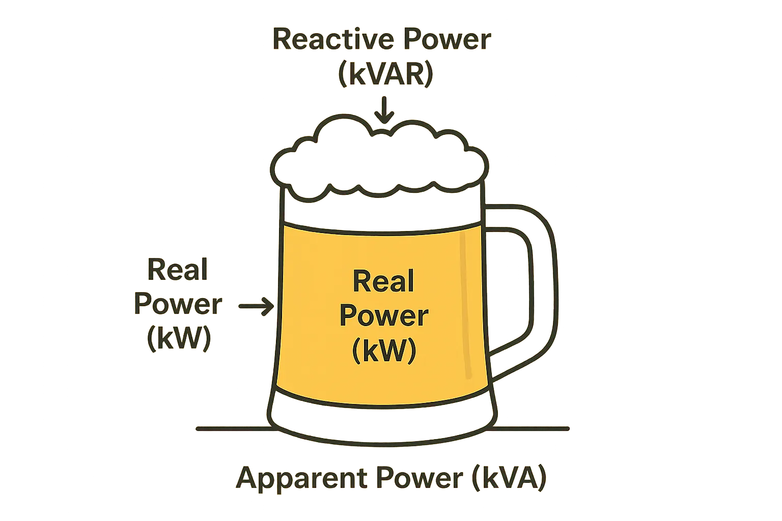
Now, here is where it gets interesting with AC power. Not all the electrical power that flows from the utility lines to a device necessarily ends up doing useful work. Some devices, especially those with motors or certain types of electronic power supplies, draw extra current that does not contribute to the main task. Think of it like this: you might be paying for a certain amount of electricity coming into your building, but not all of it is helping your equipment do what it is supposed to do. Some of it is just sloshing back and forth in the system, creating fields or charging components.
Power Factor as an Efficiency Clue
So, Power Factor gives us a number, usually between 0 and 1, that acts as a clue to this efficiency. A Power Factor of 1, or "unity," means all the power being supplied is doing useful work. That is the ideal scenario. As that number gets lower, it means a larger portion of the power is not doing direct work, and the system is less efficient at using the supplied electricity.
What Is Cos Phi?
You will often hear "Cos Phi" (Cosine of Phi) mentioned right alongside Power Factor, sometimes even used as if they are the same thing. While they are very closely related, especially in simpler electrical situations, understanding where Cos Phi comes from helps clear things up.
Understanding AC Voltage and Current
In AC systems, both the voltage and the current are not steady like in a DC battery. Instead, they continually change direction, creating a wave-like pattern. These are often called sinusoidal waves, or sine waves, because of their smooth, regular shape.
Explaining Phase Difference (Phi φ)
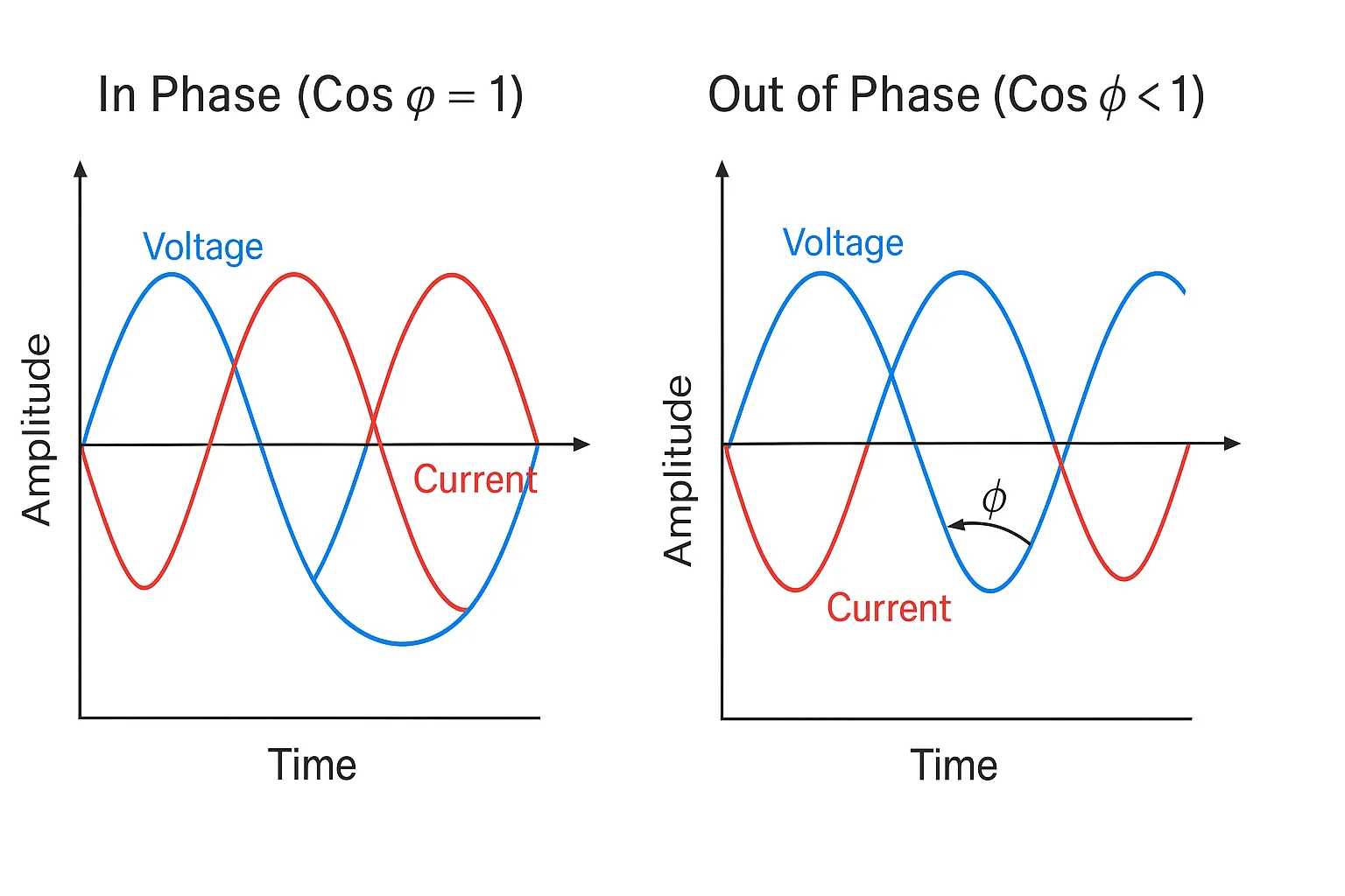
Now, imagine the voltage wave and the current wave traveling along. In a perfect scenario with a simple resistive load, like a basic electric heater, these two waves would rise and fall, and cross zero at exactly the same moments. They would be "in phase."
However, with many types of electrical loads, the current wave might lag behind the voltage wave, or sometimes lead it. This time difference between the peaks (or any corresponding points) of the voltage and current waves can be expressed as an angle. This angle is known as the phase angle, and it is represented by the Greek letter phi (φ).
Cos Phi in Simple Electrical Loads
For these simple, "linear" electrical loads where the current and voltage waveforms are still smooth sine waves (just shifted in time), the Power Factor is indeed equal to the cosine of that phase angle φ. So, Cos Phi directly tells you the Power Factor in these cases. This is where the term originates and why it is so commonly associated with Power Factor. If there is no phase difference (phi = 0 degrees), then Cos Phi is 1, and the Power Factor is 1. As the phase difference increases, Cos Phi (and thus the Power Factor for these loads) gets smaller.
Power Factor Cos Phi: The Full Picture
So far, we have talked about Power Factor mostly in the context of simple AC loads where Cos Phi tells the whole story. But the electricity powering our modern world, especially with all the electronic devices we use, is often more complex. This is where we need to look at the full picture of Power Factor.
Linear vs. Non-Linear Loads
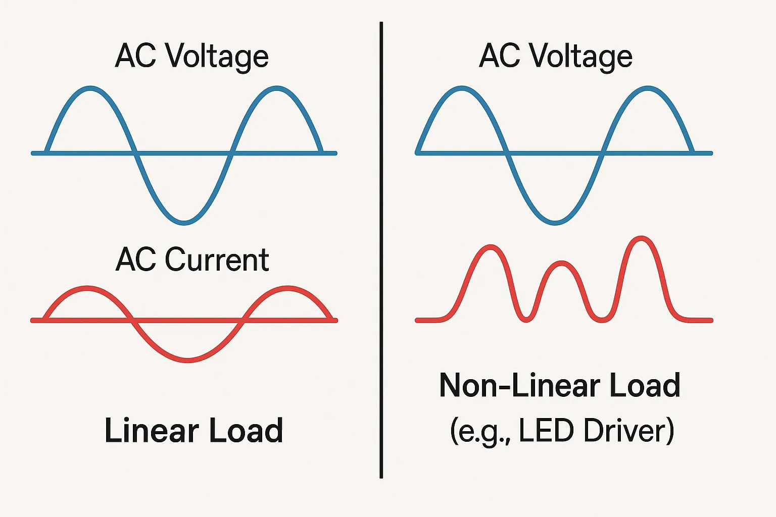
The first thing to understand is the difference between linear and non-linear electrical loads.
- Linear Loads: These are devices where the current drawn from the supply is directly proportional to the voltage, and the current waveform is a smooth sine wave, just like the voltage waveform (though it might be shifted in time, creating a phase difference). Think of simple resistive heaters or old style incandescent light bulbs.
- Non-Linear Loads: These devices draw current in a non-sinusoidal way, meaning the current waveform is distorted and does not perfectly follow the voltage waveform. Most modern electronic devices fall into this category. This includes computers, variable speed motor drives, and importantly, the electronic drivers found in most LED light fixtures.
What Are Electrical Harmonics?
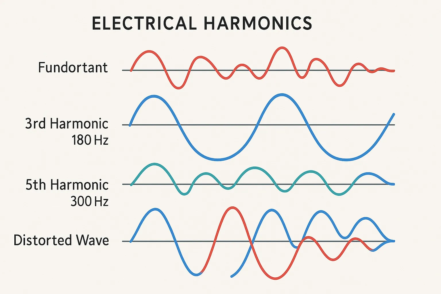
When a non-linear load draws these distorted current waveforms, something interesting happens. Mathematically, that distorted wave can be seen as being made up of the original, fundamental frequency (like 50Hz or 60Hz from your power outlet) plus a series of other waves at higher frequencies. These higher frequency waves are multiples of the fundamental frequency, and they are called electrical harmonics.
Think of it like a musical instrument. A very pure flute note might be close to a single frequency. But a distorted electric guitar sound has the main note plus a lot of other, higher pitched overtones that give it a rougher sound. Harmonics in an electrical system are a bit like those unwanted overtones. They do not usually contribute to the useful work the device is doing, but they do affect the overall current and power.
True Power Factor and Its Parts
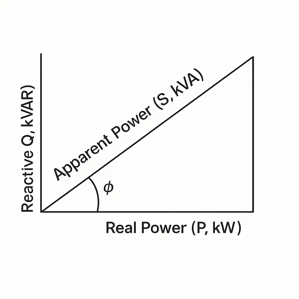
For non-linear loads that create harmonics, just looking at Cos Phi (the phase shift of the fundamental wave) is not enough to tell us the true Power Factor. We need to consider these harmonics too.
- Displacement Power Factor (DPF): This is essentially our friend Cos Phi. It measures the phase difference between the fundamental voltage and the fundamental current.
- Distortion Power Factor: This factor accounts for the harmonic distortion in the current waveform. The more harmonics, the lower this factor.
- True Power Factor (TPF): This is the real measure of power efficiency for non-linear loads. It is calculated by multiplying the Displacement Power Factor by the Distortion Power Factor (TPF = DPF × Distortion PF).
So, True Power Factor gives you the complete picture by considering both the phase shift and the waveform distortion.
Why Cos Phi Still Matters
Even with all this talk about True Power Factor and harmonics, Cos Phi (or Displacement Power Factor) is still an important number.
For many less complex non-linear loads, the harmonic distortion might be relatively small, so Cos Phi is still a very close approximation of the True Power Factor.
It is often easier to measure or specify Cos Phi.
Many regulations and standards for equipment might still refer to a minimum Cos Phi or Displacement Power Factor requirement.
It tells a key part of the story, even if it is not always the whole story for every device.
Why Is a Good Power Factor Important?
Now we get to the heart of the matter, directly answering the question in our title. Why should you, or anyone dealing with electrical systems, actually care about having a good Power Factor? There are several very practical reasons.
Less Wasted Energy in Wiring
When a system has a low Power Factor, it means more current is flowing through the wires and transformers than is necessary to do the actual work. This extra current causes more heat to be generated in the wiring due to electrical resistance (you might hear engineers talk about I²R losses). That heat is simply wasted energy, and in extreme cases, it can even cause wires to overheat. A higher Power Factor means less current for the same amount of useful work, so less energy is wasted as heat in the system's plumbing.
Better Use of System Capacity

Electrical systems, including transformers, switchgear, and cabling, are rated for the total apparent power (VA or kVA) they can handle, not just the real power (Watts). If your equipment has a low Power Factor, it draws more apparent power for the same amount of useful work. This means you are using up more of your system's capacity.
- With a high Power Factor, you can run more useful equipment on the same electrical infrastructure without overloading it.
- This can save money on new installations, as you might not need such oversized transformers or thicker cables.
Potential Savings on Energy Bills
For larger commercial and industrial electricity users, many utility companies do not just bill for the kilowatt hours (real energy) consumed. They may also have charges based on peak kVA demand, or they might directly penalize customers for having a low Power Factor.
- Improving the Power Factor in these situations can lead to direct and sometimes significant savings on the monthly electricity bill.
- Even for smaller users, less wasted energy within their own building's wiring contributes to overall energy conservation.
Longer Equipment Lifespan
The extra current drawn by low Power Factor loads can put more stress on electrical components, both in the supply system and within the equipment itself. This can lead to higher operating temperatures and potentially a shorter operational lifespan for things like transformers, motors, and even electronic power supplies. Maintaining a good Power Factor can contribute to the longevity and reliability of the entire electrical installation.
Benefits for LED Lighting Systems
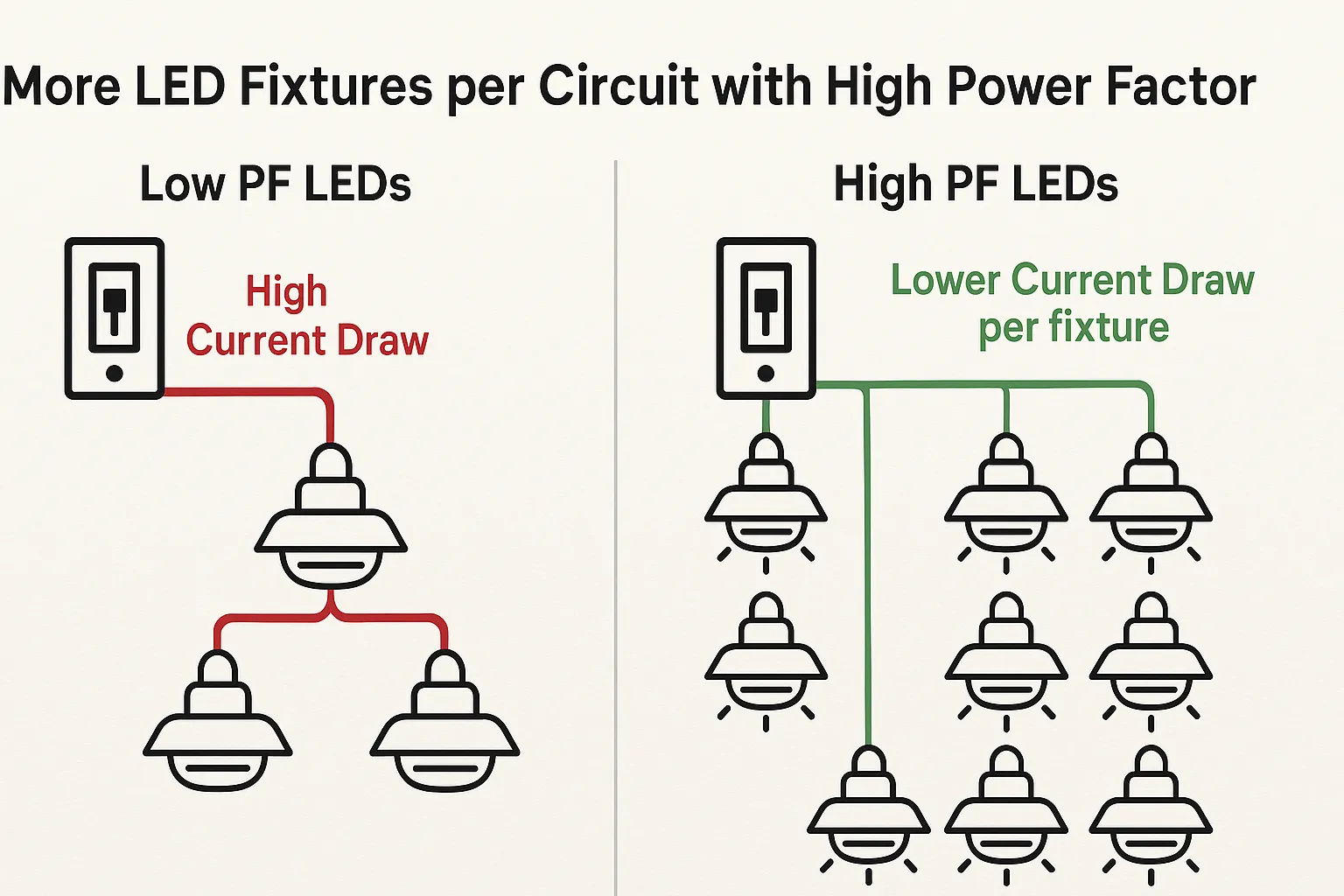
For LED lighting systems, a good Power Factor, usually achieved through well designed drivers, brings several benefits.
- More efficient drivers: Quality LED drivers with Power Factor Correction (PFC) circuits tend to be more efficient overall, meaning less energy is wasted within the driver itself.
- More fixtures per circuit: This is a big one for contractors. LED fixtures with high Power Factor draw less current for the same light output. This allows more fixtures to be safely installed on a single electrical circuit without overloading the breaker.
- System stability: In large installations with hundreds or thousands of LED fixtures, a good Power Factor across all units helps maintain better power quality and stability for the entire electrical system.
- Meeting standards: Many quality marks and energy efficiency programs (like DLC for commercial lighting in North America) require LED products to meet minimum Power Factor levels.
What Makes a Power Factor Good or Bad?
We have talked about why a good Power Factor is important, but what do those numbers actually mean? How do you know if a Power Factor value is good, acceptable, or a cause for concern?
The Power Factor Scale (0 to 1) Explained
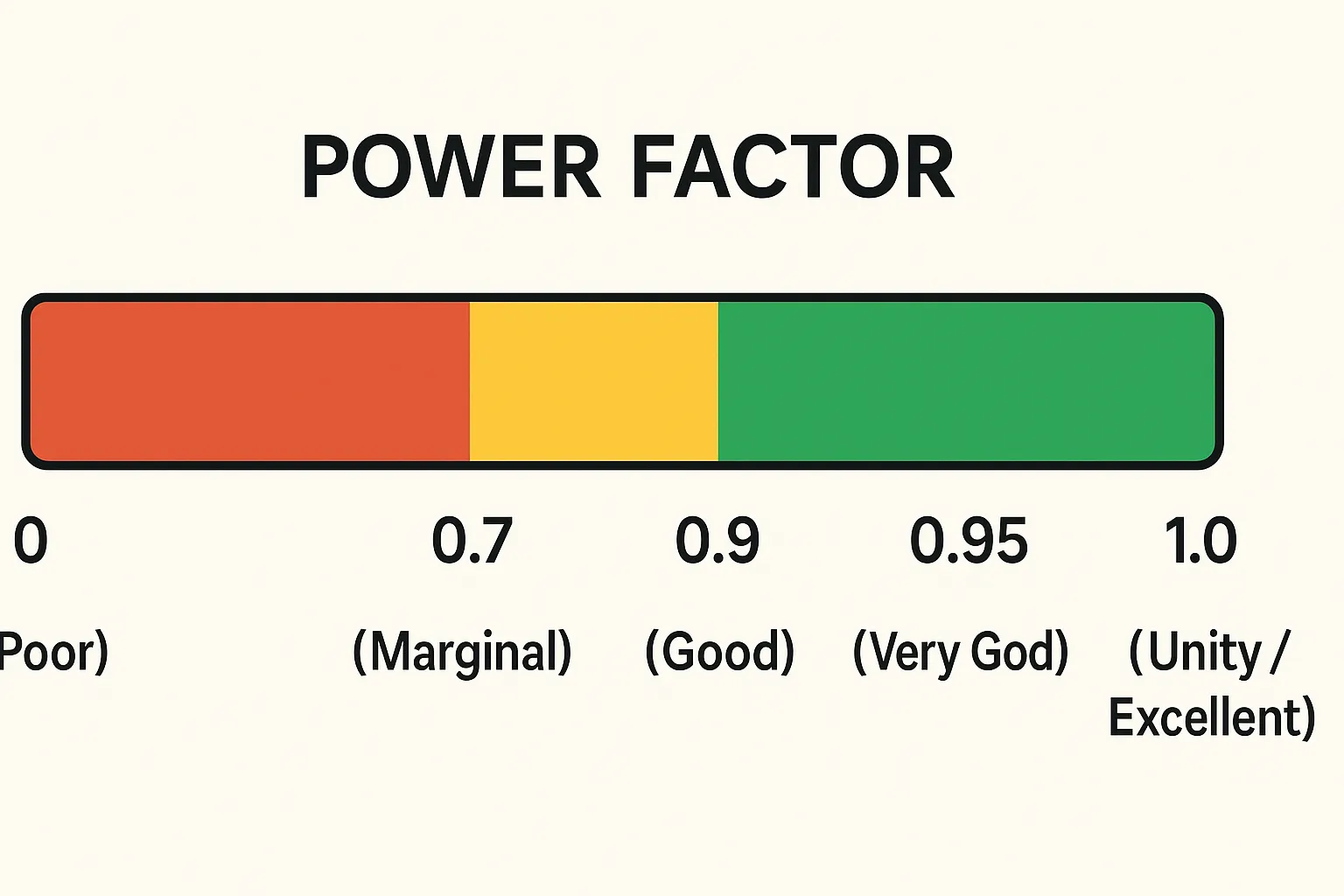
Power Factor is expressed as a number between 0 and 1.
- 1.0 (Unity): This is the perfect Power Factor. It means all the power being supplied is being used to do useful work. Purely resistive loads, like simple electric heaters or old incandescent light bulbs, have a Power Factor very close to 1.0.
- Below 1.0: Any value less than 1.0 means some portion of the power is reactive or, in the case of non-linear loads, distorted. The further the number is from 1.0, the less efficiently the supplied power is being utilized.
- You might also hear terms like "lagging" Power Factor (common with inductive loads like motors) or "leading" Power Factor (common with capacitive loads). This refers to whether the current waveform is behind or ahead of the voltage waveform.
Typical Values in Equipment
Different types of electrical equipment will naturally show a wide range of Power Factor characteristics. Some are inherently efficient in how they draw power, while others, especially older designs or those without modern power correction, can be quite poor. The table below gives a general idea of what you might encounter.
Equipment Type | Typical Power Factor (PF) Value | Brief Notes |
|---|---|---|
Incandescent Light Bulbs | Very close to 1.0 | These are almost purely resistive loads. |
Electric Motors (Older, uncorrected) | 0.6 – 0.85 (Lagging) | PF often drops further when the motor is lightly loaded. |
Fluorescent Lights (with older magnetic ballasts) | 0.5 – 0.7 (Lagging) | Older ballast technology was not very efficient in this regard. |
Modern Electronics (e.g., PCs, TVs without PFC) | 0.5 – 0.7 | Can also introduce significant harmonic distortion to the power line. |
Quality LED Fixtures (with good PFC drivers) | >0.90 (often >0.95) | Good design includes Power Factor Correction for high efficiency. |
As you can see from the table, modern, quality LED fixtures stand out with their high Power Factor values. This is largely due to the sophisticated electronic drivers they use, which incorporate active Power Factor Correction (PFC) circuits. This attention to detail by manufacturers is what separates high performance lighting from lower quality alternatives.
When Low Power Factor Is a Problem
So, when does a low Power Factor really start to cause trouble? There is no single magic number, as it can depend on the scale of the installation and the utility company's rules. However, generally:
- Many utilities start to penalize large industrial or commercial customers if their overall facility Power Factor drops below 0.90 or 0.85.
- In any installation, a Power Factor below 0.80 is usually considered poor and indicates significant inefficiencies and potential for overloading circuits.
- For individual pieces of equipment, especially electronics like LED drivers, a low Power Factor (say, below 0.7) can be a sign of a poorly designed or lower quality power supply.
Can You Improve Power Factor?
So, if a low Power Factor can cause these kinds of problems and inefficiencies, the natural next question is, can you do anything about it? The good news is, yes, in many cases, Power Factor can be improved. This process is generally known as Power Factor Correction.
What Is Power Factor Correction (PFC)?
Power Factor Correction, or PFC, refers to techniques and technologies used to increase the Power Factor of an electrical load, or an entire electrical system, closer to the ideal value of 1.0. The basic idea is to compensate for the reactive power that the load is drawing, or to reduce the harmonic distortion it creates, so that the apparent power drawn from the source is closer to the real power being consumed. This makes the whole system work more efficiently.
PFC in Modern Electronics
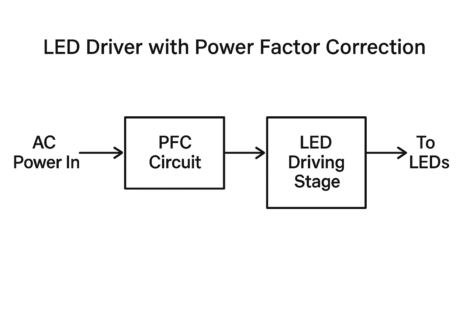
You will find that many modern electronic devices, especially those using switch-mode power supplies (which is a lot of them these days), often have PFC circuits built right into them. Manufacturers do this for a few reasons.
- Sometimes it is to meet energy efficiency regulations or standards that require a minimum Power Factor for certain types of equipment.
- It also makes their products better citizens on the electrical grid, drawing power more cleanly.
- For example, good quality LED drivers almost always include active PFC circuits. This ensures the LED fixtures themselves operate with a high Power Factor, making them efficient right out of the box and easy for contractors to integrate into building electrical systems.
System Level Correction Methods
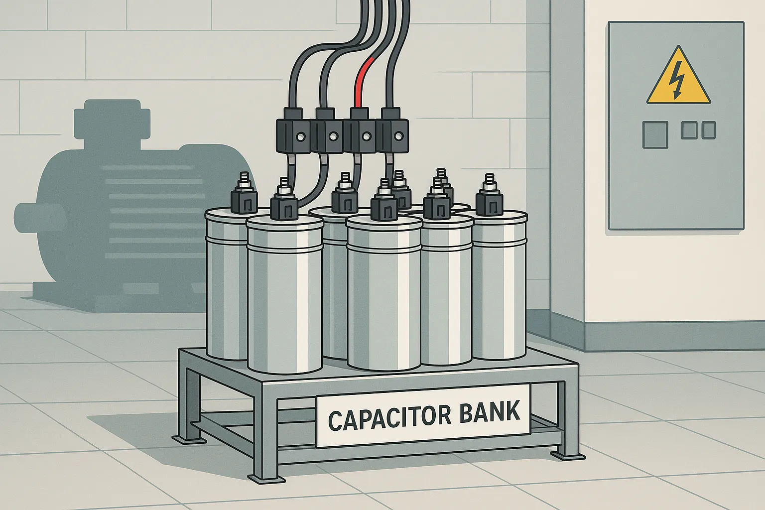
For larger facilities, like factories or big commercial buildings that might have a lot of inductive loads (think many large motors), sometimes Power Factor correction is done at the overall system level, rather than just within each piece of equipment.
The most common method here is installing banks of capacitors. These capacitors provide leading reactive power to offset the lagging reactive power drawn by inductive loads.
In some very large industrial applications, other technologies like synchronous condensers or active harmonic filters might be used.
These system-level solutions are usually designed and installed by specialized electrical engineers based on a detailed analysis of the facility's electrical loads.
Power Factor Cos Phi: A Mark of Quality and Efficiency
So, as we have explored, Power Factor Cos Phi is not just some obscure technical term. It really tells you how efficiently electrical energy is being used in a system. This includes modern LED lighting.
A high, well-maintained power factor simply means less wasted energy. It also means better use of your electrical infrastructure and can often lead to lower operating costs for the end user.
For any professional involved with electrical work, from specifying equipment to installing it, paying close attention to power factor is just plain smart. It is a direct reflection of good engineering and how efficiently energy gets used on the job.

At Sparkle Star, we take this idea of electrical efficiency very seriously. We know that a truly excellent lighting product has to perform well electrically, not just look good or be bright.
That is why achieving a high Power Factor Cos Phi is a fundamental part of how we design and make all our LED fixtures. This applies across our extensive range, including our linear lights, cabinet lights, closet lights, office lights, outdoor lights, and our popular track lighting systems.
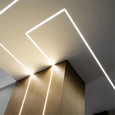
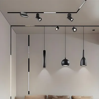


Our unwavering focus on careful engineering and strict quality control means Sparkle Star fixtures not only deliver brilliant illumination but also operate with outstanding electrical efficiency, consistently meeting or exceeding industry benchmarks. We believe this provides a real advantage.
We invite you to see the Sparkle Star difference for yourself. Explore our detailed product specifications, or reach out to our team to discuss how our high Power Factor Cos Phi LED lighting solutions can enhance your offerings and benefit your customers. We are confident you will find that partnering with Sparkle Star means choosing quality and performance you can depend on.
Frequently Asked Questions About Power Factor Cos Phi
Here are answers to some common questions that arise when dealing with Power Factor Cos Phi and its implications for electrical systems, including various types of LED fixtures.
Q: Can a low Power Factor Cos Phi damage LED fixtures?
A: Generally, a low Power Factor Cos Phi in an LED fixture itself points more to an inefficient driver design than something that directly harms the LED chips, assuming the driver provides stable power. However, a poorly designed driver with low PF might operate at higher temperatures or put more stress on its own internal components. This could potentially shorten the lifespan of the driver, leading to premature fixture failure, even if the LEDs themselves are still good.
Q: How does Power Factor Cos Phi relate to THD in LED lighting?
A: They are definitely related when you are talking about non-linear loads like LED drivers. As we touched on, True Power Factor is a product of Displacement Power Factor (which is Cos Phi) and Distortion Power Factor. Total Harmonic Distortion, or THD, is a measure of that waveform distortion caused by harmonics. A high THD leads to a low Distortion Power Factor. So, even if your Cos Phi (phase alignment) is good, high THD will still pull down your True Power Factor. Quality LED products aim for both a high Cos Phi and low THD.
Q: Are there simple ways for contractors to check Power Factor Cos Phi on site?
A: For individual fixtures, not really without specialized equipment like a power quality analyzer. Most contractors will rely on the specifications provided by the fixture manufacturer. For an entire circuit with multiple loads, an electrician might use an advanced clamp meter that can give a Power Factor reading for that circuit, but it will be an aggregate value. The most reliable approach for specific types of LED fixtures is to work with manufacturers who provide accurate and trustworthy technical data.
Q: Do all regions have the same Power Factor Cos Phi standards for lighting?
A: No, the specific minimum Power Factor Cos Phi requirements or recommendations for lighting equipment can vary. For instance, Europe has certain EN standards that address harmonics and by extension, power factor, for electronic devices. In North America, programs like DLC (DesignLights Consortium) often stipulate minimum power factor levels for LED fixtures to qualify for utility rebates. It is always a good practice for distributors and contractors to be aware of the relevant local or project-specific standards.
Q: If I stock LED fixtures with high Power Factor Cos Phi, what is the direct advantage for my distribution business?
A: Stocking LED fixtures with a high Power Factor Cos Phi offers several clear advantages for your business. First, you are providing your contractor customers with higher quality, more efficient products, which enhances your reputation as a supplier of choice. Second, because high PF fixtures draw less current for the same light output, contractors can often install more units on a single circuit, saving them time and installation costs. Finally, these fixtures can help end-users reduce their overall energy waste and potentially meet utility requirements, making them an easier sell. At Sparkle Star, when we design our various types of LED fixtures, achieving an excellent Power Factor Cos Phi is a top priority. We do this to ensure you, our distributor partner, can offer truly efficient and reliable lighting solutions that bring these tangible benefits to your customers.


